
Difficulty
Moderate
Steps
14
Time Required
20:00:00
- Chromance Assembly Instructions 14 steps

Featured Guide
This guide has been found to be exceptionally cool by the site's staff.
Quiz
0
Introduction
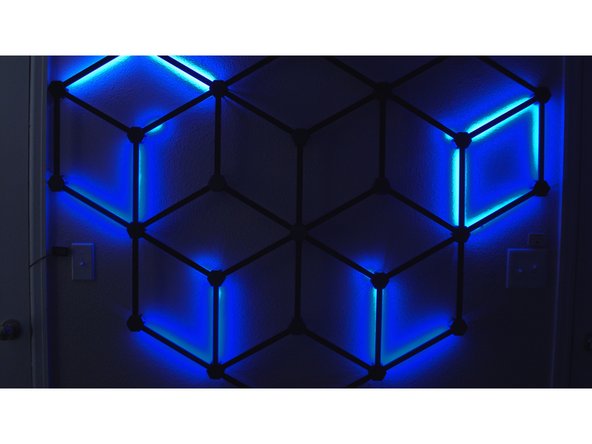
Turn your most boring wall into a big statement with this lavishly illuminated RGB decoration. It's easy to assemble and looks phenomenal - and if you have an EmotiBit, it'll even visualize your heartbeats and sweat spikes in perfectly synchronized pulses.
Watch the video: https://www.youtube.com/watch?v=g6n8XLmZ...
Download the firmware: https://github.com/ZackFreedman/Chromanc...
Grab the STL's: https://thangs.com/ZackFreedman/Chromanc...
Bill of Materials:
- 10m LED channel w/ white diffuser, pref. black - https://amzn.to/3nFEC3w
- 10m DotStar LED tape, 60 pixels/m - https://www.adafruit.com/product/2239?le...
- OR: 10m WS2812B (NeoPixel) LED tape, 60 pixels/m - https://amzn.to/3gTGzYS
- 1x Node32S-style ESP32 module - https://amzn.to/2QO9brO
- 2.54mm headers - https://amzn.to/3ujX4S0
- 1x 8-position 2.54mm-pitch terminal - https://amzn.to/3uerfKd
- 1x 2-position 5mm-pitch terminal - https://amzn.to/3gU5WJV
- 1x 2.1mm barrel jack, PCB mount - https://amzn.to/33bmpRS
- Stripboard - https://amzn.to/3aXs2Yc
- Epoxy (I like JB Kwik-Weld) - https://amzn.to/3xHL1jp
- 5V PSU w/ 2.1mm barrel plug 5A or higher - https://amzn.to/2RkIL0A
- 1/2" wide double stick tape, at least 3m - https://amzn.to/3gT8mst
- 3D printer filament - I used carbon-fiber PLA - https://amzn.to/3xHIwh6
- Lots of wire, solder, and flux
- Hot glue
-
-
Print the following:
-
1x TopLeftNode.stl
-
1x TopRightNode.stl
-
3x TopCenterNode.stl
-
20x RegularNode.stl
-
I used carbon fiber PLA. Nail that first layer - it's what people will see.
-
The Top nodes must be printed with supports everywhere. The Regular nodes do not need supports.
-
-
-
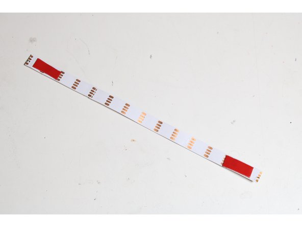
Cut 40 segments of LED strips, 14 LED's long.
-
Don't cut off too much of the pads on the ends! We need to solder to it!
-
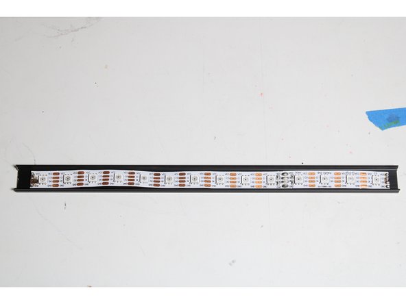
Cut 40 segments of aluminum extrusion, 25cm each. Deburr the ends so they don't cut into the strips!
-
Cut 40 segments of diffuser plastic, 23cm each.
-
The diffusers should be shorter than the aluminum, or they'll be difficult to snap onto the extrusion after the system is assembled.
-
-
-
Use some heat-tolerant double-stick tape to mount a strip to the center of each aluminum segment.
-
Don't put tape too close to the ends! It'll burn when we solder the strips!
-
The tape may not be necessary if your strips are particularly wide. If the channel in the extrusion holds the strip securely on its own, no tape is needed.
-
-
-
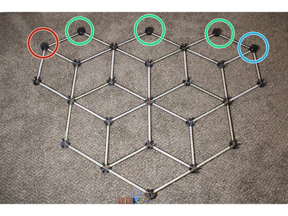
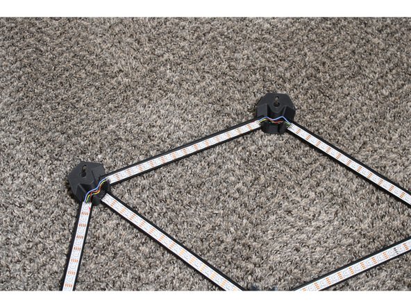
Assemble the network - but don't glue it yet! Remember that the node names are backwards, because this is sitting upside-down.
-
TopRightNode goes here.
-
TopCenterNodes go here
-
TopLeftNode goes here
-
All other nodes are RegularNodes.
-
Make sure the strips face the directions indicated. There should be arrows on the strips, but if there aren't, the pads named DI and CI are the start of the strips, and DO and CO are the end.
-
-
-
Before continuing, make absolutely sure that the strips and hubs are correctly oriented.
-
Double-check that the Top piece keyholes have the narrow bit facing up, and the circular bit facing down.
-
Seriously, be careful. This glue is permanent.
-
Mixing small batches at a time, epoxy the segments into the hubs. They should bottom out into their slots.
-
Ventilate the room with fresh air, and allow the epoxy to fully cure before continuing.
-
-
-
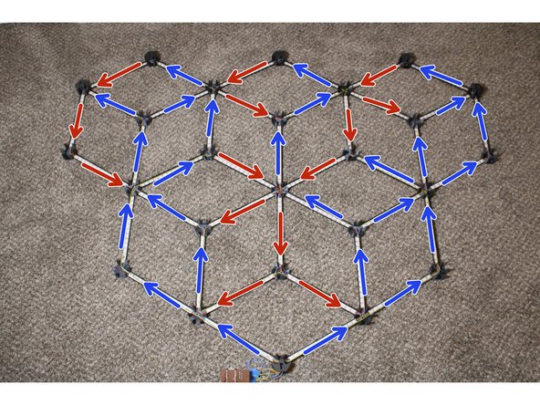
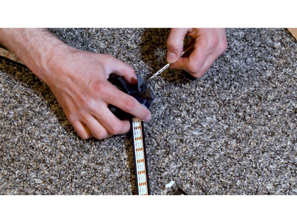
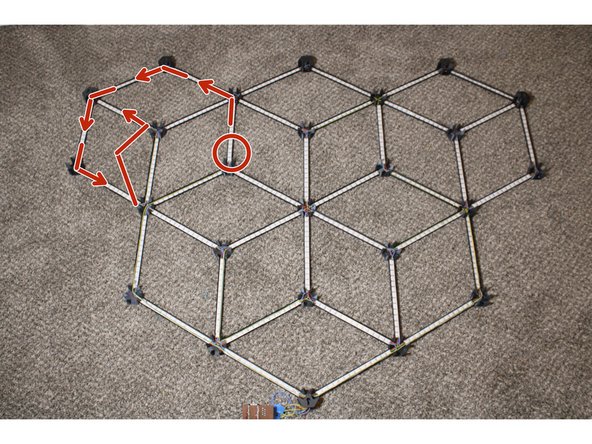
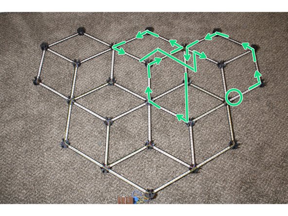
In the accompanying diagram, locate the strip marked with a red circle. Solder a wire to the pads marked DO and CO at the end of that strip, where the arrow begins.
-
Follow the arrow to the next strip. Solder the DO wire to that strip's DI pad, and the CO wire to the CI pad.
-
Continue soldering DO to DI and CO to CI, to link each strip to the next strip connected an arrow. Repeat for the black and green diagrams.
-
NeoPixels don't have CO and CI pins. If you're using NeoPixels, connect the DO and DI pins as instructed, but forget about CO and CI pins.
-
Do not solder wires to the DI and CI pads of the first strip in each diagram yet. The DO and CO pads of the final strip in each diagram shouldn't have anything soldered to them, either.
-
Due to the tutorial software's limits, the fourth strip sequence is shown in the following step.
-
-
-
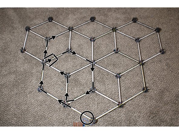
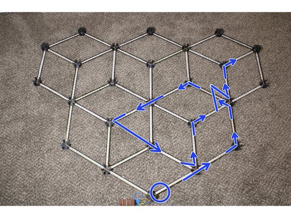
Solder up the last group of strips, starting with the strip circled blue and following the arrows.
-
Some connected strips don't share a hub - you need to run these wires in parallel with strips. Use hot glue to tack these to the side so they don't block any LED's.
-
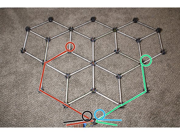
Solder wires to the DI and CI pads of the first strip in each of the four diagrams. These are circled in the diagrams. Route the wires out of the bottom node.
-
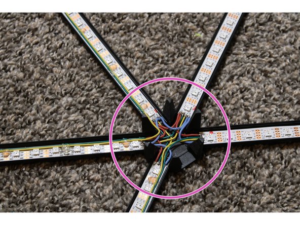
At each hub, wire all the VCC pads together, then wire all the GND pads together. DO NOT connect any VCC pad to GND.
-
Solder wires to the two VCC and two GND pads in the bottom node and route them out the bottom.
-
-
-
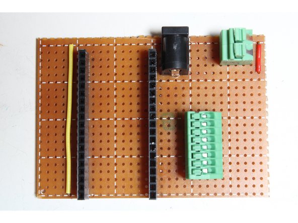
Cut a segment of stripboard 21x30 holes wide.
-
Using a sharp knife or Veroboard tool, split the stripboard’s copper conductors where indicated by green lines.
-
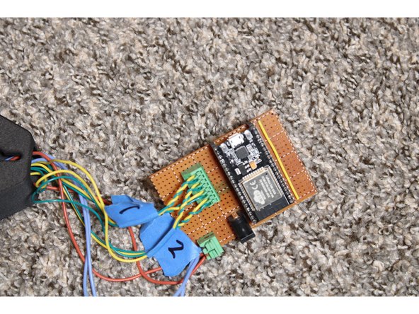
Solder in two wire jumpers, a 2.1mm jack, two female 19-position headers, a 5mm 2-position terminal, and a 2.54mm 8-position terminal as shown.
-
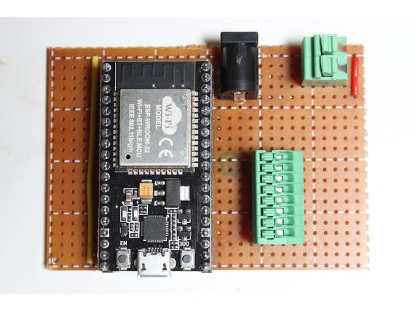
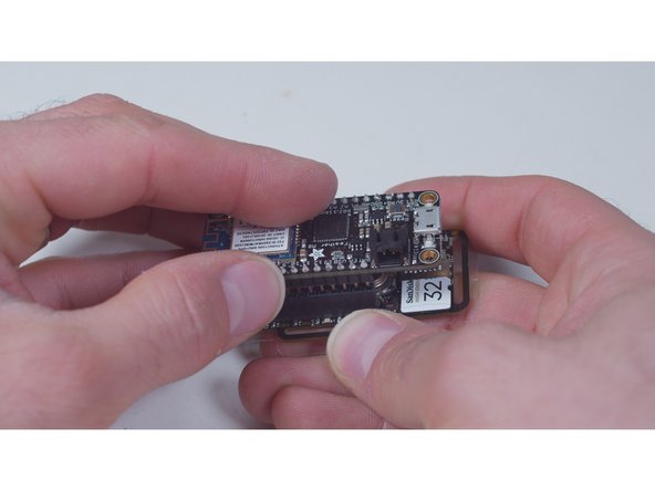
Solder headers to the Node32S module and mount it.
-
-
-
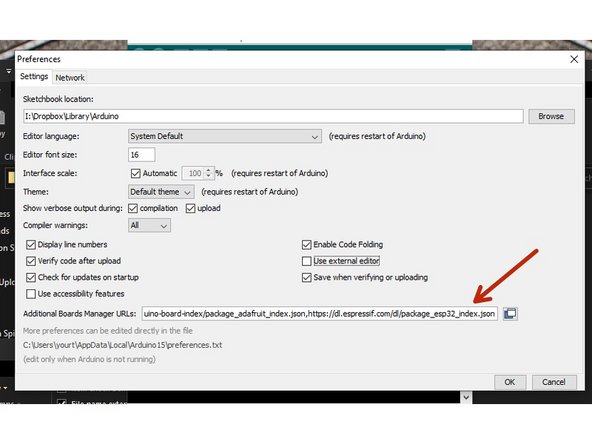
Open the Arduino software and open its Preferences. Add the following to the Additional Boards Manager URLs field, then restart Arduino: https://dl.espressif.com/dl/package_esp3...
-
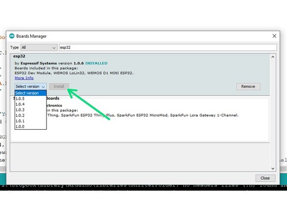
Navigate to Tools --> Board --> Boards Manager. Find 'esp32' and install it.
-
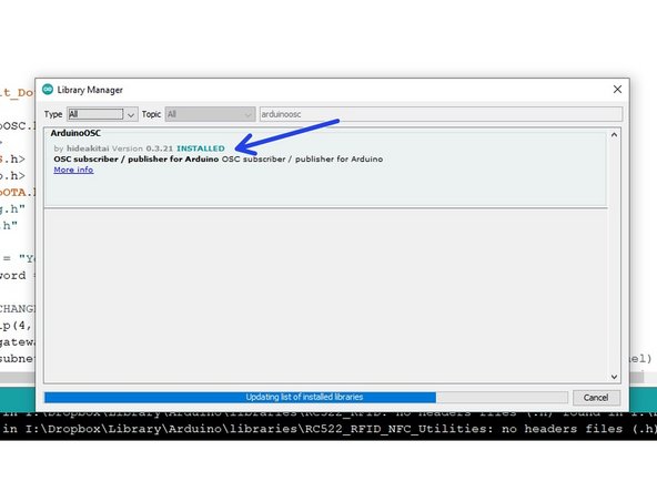
Navigate to Tools --> Manage Libraries. Install Adafruit_DotStar, ArduinoOSC, and ArduinoOTA.
-
Plug the ESP32 module into your computer and allow any drivers to load.
-
DO NOT PLUG YOUR ESP32 MODULE INTO YOUR COMPUTER WHILE THE STRIPS ARE CONNECTED. IT MAY DESTROY YOUR COMPUTER.
-
-
-
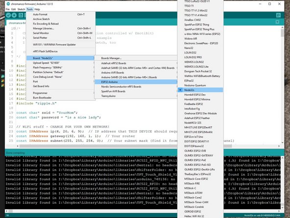
Select your ESP32's serial port. Pick Tools --> Board --> ESP32 Arduino --> Node32s.
-
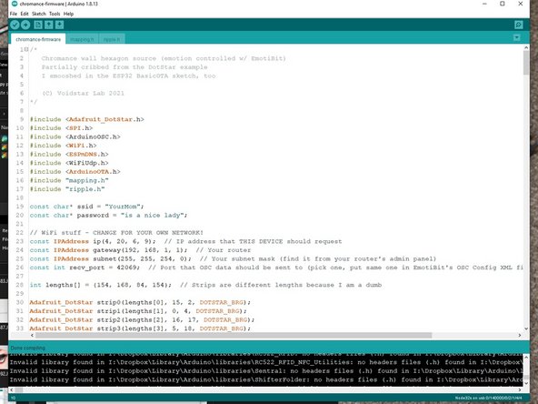
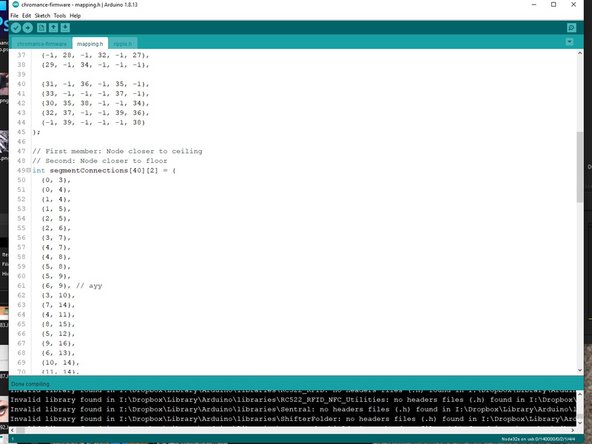
Open the firmware. Change the SSID, password, Gateway, and Subnet to fit your router configuration. Pick an IP address that's unused, preferably outside your router's DHCP range. Pick a recv_port, ideally above 16000.
-
Upload the firmware. Allow the ESP32 to reboot and connect to the network.
-
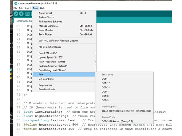
Go to Tools --> Port and look for a Network Port. If you see your selected IP address, you're ready for OTA updates! Your USB cable is no longer necessary.
-
If you don't see your device, I dunno. Ask on the Voidstar Lab Discord!
-
-
-
Connect the DIN and CIN pins to the appropriate terminals.
-
Strip 1 (marked with blue arrows in previous diagrams) goes in the terminals furthest from the jack.
-
Strip 2 (marked green) is next
-
Then Strip 3 (marked red)
-
Finally, Strip 4 (marked black)
-
The DIN lines are further from the jack (yellow wires in my picture) and CIN lines are closer.
-
Put the VCC wires into the left 5mm terminal, and the GND wires into the right.
-
Plug in the PSU and plug it into the jack. If your project catches fire, you've made a mistake.
-
-
-
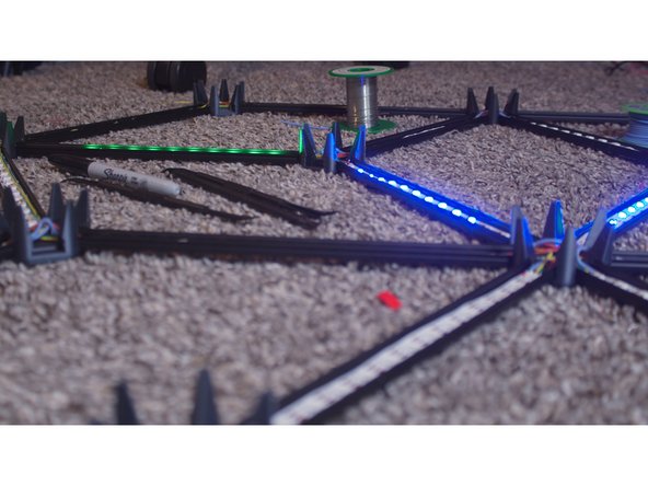
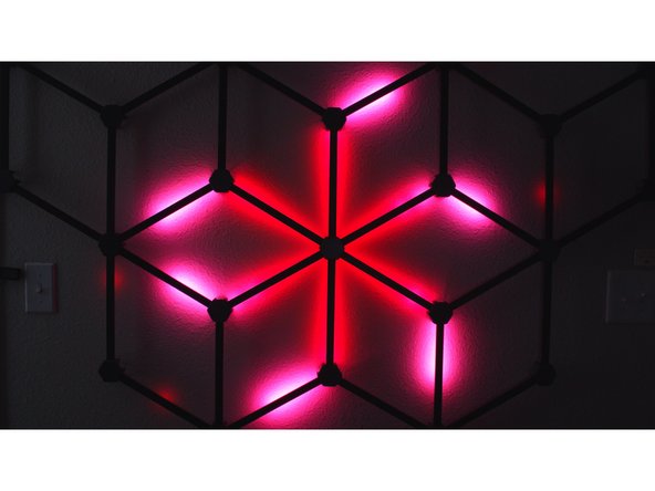
Watch the ripples. They should begin after a few seconds and proceed smoothly through all strips.
-
If one or more strips fails to light up, check for shorts, breaks, and boo-boos. Pads can get ripped off very easily - in that case, remove and replace that strip.
-
If a ripple jumps around on a specific strip, it may be backwards. Adjust mapping.h to reverse it. The nodes and strips are numbered right to left, top to bottom.
-
-
-
An EmotiBit is not necessary to use the Chromance, but it makes it way cooler!
-
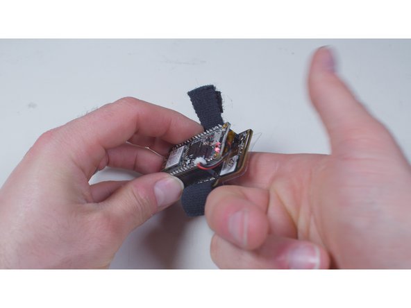
Assemble, charge, and configure your EmotiBit as instructed by the manufacturer.
-
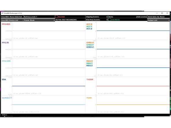
Download, install, and open the EmotiBit Oscilloscope. Then close it!
-
Open C:\Program Files\EmotiBit\EmotiBit Oscilloscope\data\oscOutputSettings.xml (or whatever it is on Linux or Mac). Edit the <output> section to match the IP address and port you put in the firmware earlier.
-
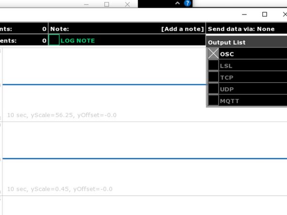
Connect your EmotiBit, and enable OSC in the Output List.
-
-
-
Put your EmotiBit on and ensure data is streaming through the Oscilloscope
-
Your heartbeats and EDA changes should immediately start firing ripples through the Chromance!
-
Adjust the biometric settings in the firmware to respond accurately to your emotional state.
-
Set up a chair, smoke a fat (legal in Colorado) doobie, and enjoy the show.
-
If you enjoyed the project and want to support the next one, head to patreon.com/zackfreedman and give me a huge pile of money!
-
You rule.
-


Cancel: I did not complete this guide.
16 other people completed this guide.
31 Comments
@zackfreedman Awesome project!!! Any instructions for using WLED? I won't be using an Emotibit but would like Audio Reactive along with your pre-programed rainbow pattern.
David Cornelius - Resolved on Release Reply
Made my own channels and diffusers and made a junction box for the electronics including a power plug, on off button and usb access for the ESP32.
Adding my own variant here. Took @hastypete bottom node and added a controller box for the ESP32 Dev Breakout Board I used instead of Stripboard.
Timothy Gleason - Resolved on Release Reply
After making my own I was looking at the hubs and had the idea of modifying the hubs to have a single peg instead of 6 all around.
I'm attaching a link to my stl files.
The other thing is that I discovered that you only need two of the special top nodes. The whole structure is light enough for two screws. So I did not modify the "left" and "right" top nodes.
Also I did some creativity for a bottom node. It is 50% larger and has room for the ESP32 board. It also has a support and hole for the standard barrel connector that comes with the standard power supply in the list.
I haven't finished the one with the new hubs, I'll put a photo in the share when I get it done.
I did put a photo of what the "brain" node looks like.
I saw that you are now using WLED for the Chromance. How should I configure it, to make mine work the same way yours does?
Could you create a branch on the Chromance github with the code you are currently using? And since I don't want to use an Emotibit, how well does the WLED integration work without one?
Thank you in advance and also thanks for creating amazing projects. You inspire me to stop procrastinating and make some projects. :)
Felix Schuster - Resolved on Release Reply