
Difficulty
Moderate
Steps
14
Time Required
20:00:00
- Chromance Assembly Instructions 14 steps

Featured Guide
This guide has been found to be exceptionally cool by the site's staff.
Quiz
0
Introduction
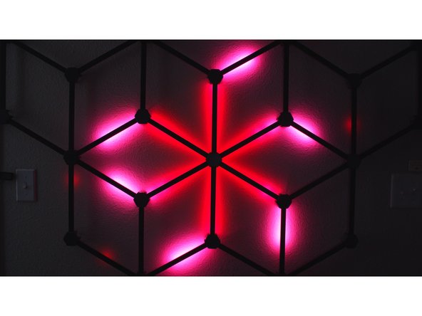
Turn your most boring wall into a big statement with this lavishly illuminated RGB decoration. It's easy to assemble and looks phenomenal - and if you have an EmotiBit, it'll even visualize your heartbeats and sweat spikes in perfectly synchronized pulses.
Watch the video: https://www.youtube.com/watch?v=g6n8XLmZ...
Download the firmware: https://github.com/ZackFreedman/Chromanc...
Grab the STL's: https://thangs.com/ZackFreedman/Chromanc...
Bill of Materials:
- 10m LED channel w/ white diffuser, pref. black - https://amzn.to/3nFEC3w
- 10m DotStar LED tape, 60 pixels/m - https://www.adafruit.com/product/2239?le...
- OR: 10m WS2812B (NeoPixel) LED tape, 60 pixels/m - https://amzn.to/3gTGzYS
- 1x Node32S-style ESP32 module - https://amzn.to/2QO9brO
- 2.54mm headers - https://amzn.to/3ujX4S0
- 1x 8-position 2.54mm-pitch terminal - https://amzn.to/3uerfKd
- 1x 2-position 5mm-pitch terminal - https://amzn.to/3gU5WJV
- 1x 2.1mm barrel jack, PCB mount - https://amzn.to/33bmpRS
- Stripboard - https://amzn.to/3aXs2Yc
- Epoxy (I like JB Kwik-Weld) - https://amzn.to/3xHL1jp
- 5V PSU w/ 2.1mm barrel plug 5A or higher - https://amzn.to/2RkIL0A
- 1/2" wide double stick tape, at least 3m - https://amzn.to/3gT8mst
- 3D printer filament - I used carbon-fiber PLA - https://amzn.to/3xHIwh6
- Lots of wire, solder, and flux
- Hot glue
-
-
Print the following:
-
1x TopLeftNode.stl
-
1x TopRightNode.stl
-
3x TopCenterNode.stl
-
20x RegularNode.stl
-
I used carbon fiber PLA. Nail that first layer - it's what people will see.
-
The Top nodes must be printed with supports everywhere. The Regular nodes do not need supports.
-
-
-
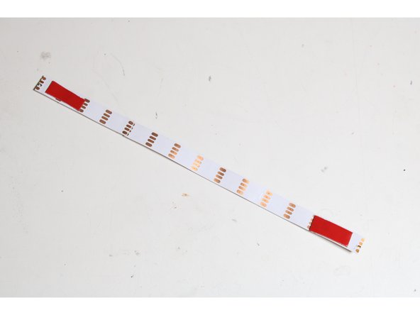
Cut 40 segments of LED strips, 14 LED's long.
-
Don't cut off too much of the pads on the ends! We need to solder to it!
-
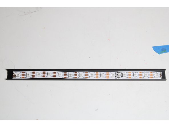
Cut 40 segments of aluminum extrusion, 25cm each. Deburr the ends so they don't cut into the strips!
-
Cut 40 segments of diffuser plastic, 23cm each.
-
The diffusers should be shorter than the aluminum, or they'll be difficult to snap onto the extrusion after the system is assembled.
May I suggest to cut one of each, confirm the length then proceed with the other 39 :P
It might save someone a headache.
Simon Benoit - Resolved on Release Reply
What type of cutter should I use to cut the LED strips?
Aryan Prodduturi - Resolved on Release Reply
Scissors are fine, and a sharp razor blade will also work. Just try to slice straight through the middle of the pads, so you leave enough metal on both strips to solder!
-
-
-
Use some heat-tolerant double-stick tape to mount a strip to the center of each aluminum segment.
-
Don't put tape too close to the ends! It'll burn when we solder the strips!
-
The tape may not be necessary if your strips are particularly wide. If the channel in the extrusion holds the strip securely on its own, no tape is needed.
-
-
-
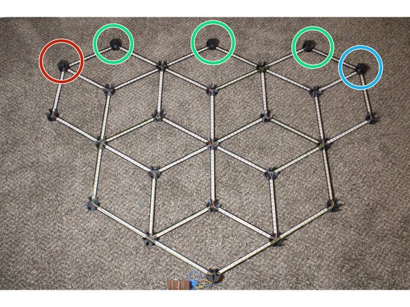
Assemble the network - but don't glue it yet! Remember that the node names are backwards, because this is sitting upside-down.
-
TopRightNode goes here.
-
TopCenterNodes go here
-
TopLeftNode goes here
-
All other nodes are RegularNodes.
-
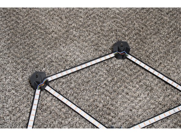
Make sure the strips face the directions indicated. There should be arrows on the strips, but if there aren't, the pads named DI and CI are the start of the strips, and DO and CO are the end.
I think you need a top center node at the bottom as well, so you actually need 4x in step 1 (and -1 in regulars) and one more circled out here in the first picture.
Diego Della Valle - Resolved on Release Reply
The arrow is still missing for me. Should the direction of that strip be up/left or down/right?
Gary Woodhouse - Resolved on Release Reply
In the 2nd image, what I suppose is the last segment (top left), hasn’t got a “direction arrow” on top. Not strictly necessary but is messing with my OCD, I urge you to fix it.
Pietro Pasquero - Resolved on Release Reply
-
-
-
Before continuing, make absolutely sure that the strips and hubs are correctly oriented.
-
Double-check that the Top piece keyholes have the narrow bit facing up, and the circular bit facing down.
-
Seriously, be careful. This glue is permanent.
-
Mixing small batches at a time, epoxy the segments into the hubs. They should bottom out into their slots.
-
Ventilate the room with fresh air, and allow the epoxy to fully cure before continuing.
-
-
-
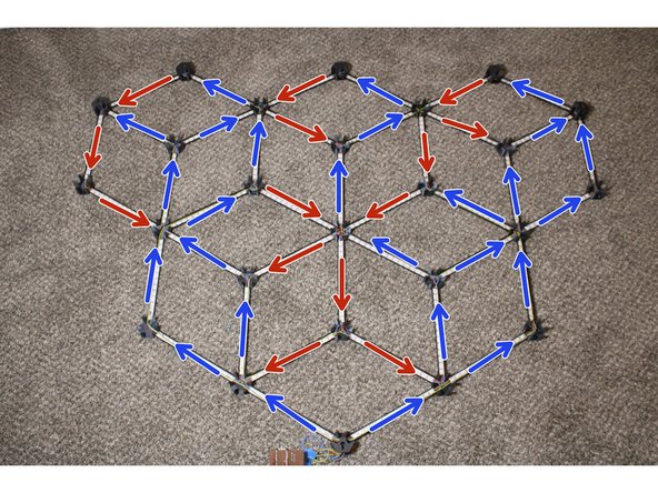
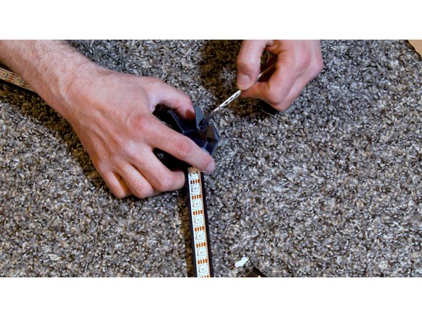
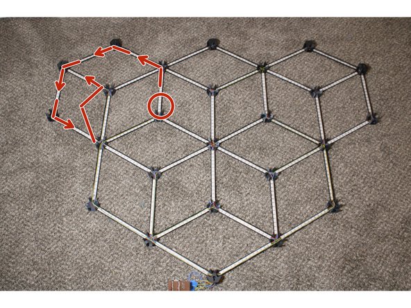
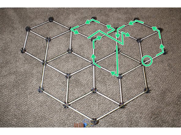
In the accompanying diagram, locate the strip marked with a red circle. Solder a wire to the pads marked DO and CO at the end of that strip, where the arrow begins.
-
Follow the arrow to the next strip. Solder the DO wire to that strip's DI pad, and the CO wire to the CI pad.
-
Continue soldering DO to DI and CO to CI, to link each strip to the next strip connected an arrow. Repeat for the black and green diagrams.
-
NeoPixels don't have CO and CI pins. If you're using NeoPixels, connect the DO and DI pins as instructed, but forget about CO and CI pins.
-
Do not solder wires to the DI and CI pads of the first strip in each diagram yet. The DO and CO pads of the final strip in each diagram shouldn't have anything soldered to them, either.
-
Due to the tutorial software's limits, the fourth strip sequence is shown in the following step.
-
-
-
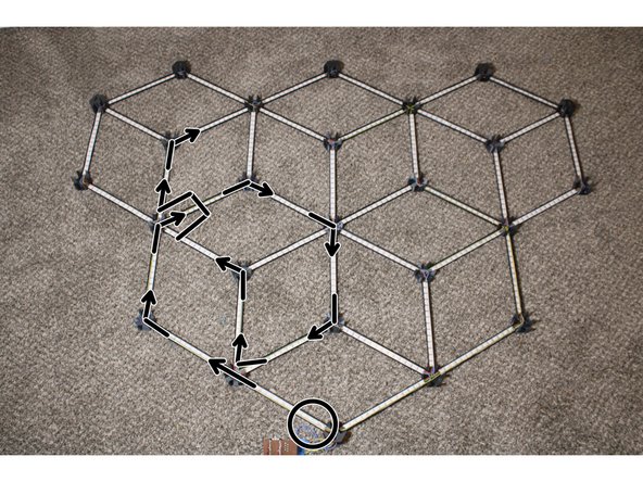
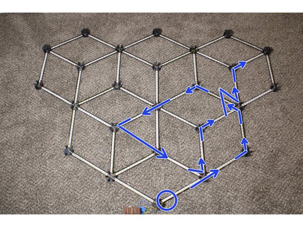
Solder up the last group of strips, starting with the strip circled blue and following the arrows.
-
Some connected strips don't share a hub - you need to run these wires in parallel with strips. Use hot glue to tack these to the side so they don't block any LED's.
-
Solder wires to the DI and CI pads of the first strip in each of the four diagrams. These are circled in the diagrams. Route the wires out of the bottom node.
-
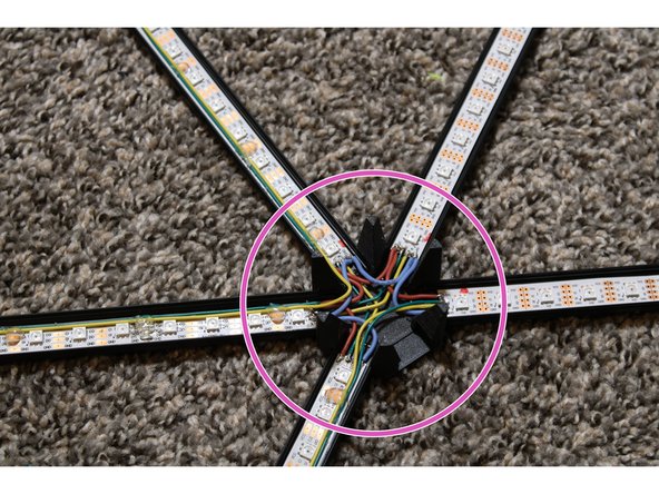
At each hub, wire all the VCC pads together, then wire all the GND pads together. DO NOT connect any VCC pad to GND.
-
Solder wires to the two VCC and two GND pads in the bottom node and route them out the bottom.
-
-
-
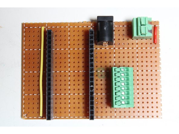
Cut a segment of stripboard 21x30 holes wide.
-
Using a sharp knife or Veroboard tool, split the stripboard’s copper conductors where indicated by green lines.
-
Solder in two wire jumpers, a 2.1mm jack, two female 19-position headers, a 5mm 2-position terminal, and a 2.54mm 8-position terminal as shown.
-
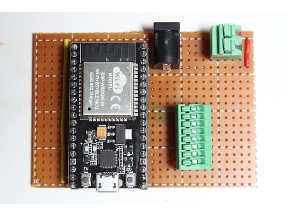
Solder headers to the Node32S module and mount it.
Just to have it crystal clear in my pleb like brain, first pic displaying the green lines to break circuit, the sort, 2nd from the left, top, that’s breaking the first 3 lines, not 4, correct? Sorry for the noob question!
Bo Pedersen - Resolved on Release Reply
The barrel jack pins from the BoM doesn’t align with the stripboard rows like in the image. Should I force the front and back pins to be on the same rows as the red jumper wire, with middle pins lining up with GND on the ESP32? It also might be helpful to have a “Prep for component soldering” step that instructs to cut headers to size, snip every other pin on the 8-position terminal, and space out the barrel jack pins (if that’s correct)
You can just drill a hole in the board or jump it over - as long as it’s securely fixed to the board and connected to the right traces, you’re fine.
-
-
-
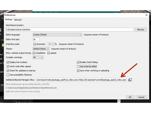
Open the Arduino software and open its Preferences. Add the following to the Additional Boards Manager URLs field, then restart Arduino: https://dl.espressif.com/dl/package_esp3...
-
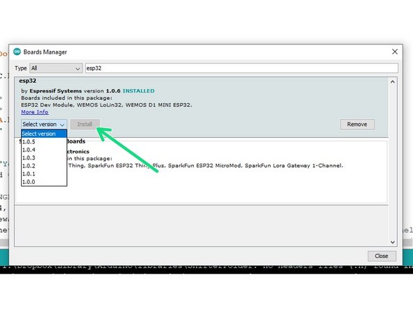
Navigate to Tools --> Board --> Boards Manager. Find 'esp32' and install it.
-
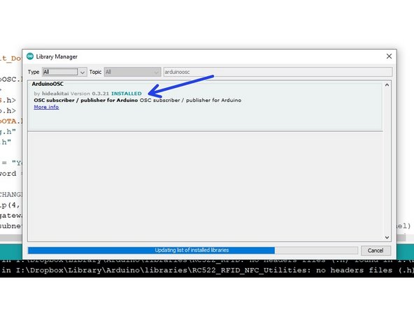
Navigate to Tools --> Manage Libraries. Install Adafruit_DotStar, ArduinoOSC, and ArduinoOTA.
-
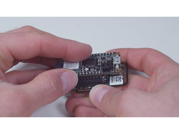
Plug the ESP32 module into your computer and allow any drivers to load.
-
DO NOT PLUG YOUR ESP32 MODULE INTO YOUR COMPUTER WHILE THE STRIPS ARE CONNECTED. IT MAY DESTROY YOUR COMPUTER.
In case others might be scratching their bald head like I was, when after plugging in said board to my i-wish-it-was-still-windows-10-pc, rrrr, ummm - pc, and nothing happened - windows update was blind as well. THIS:->> https://www.silabs.com/developers/usb-to... <<- is the driver that made joy happen, if your ESP32 has a CP210x USB to UART Bridge. Cheers!
Bo Pedersen - Resolved on Release Reply
ESPmDNS & WiFiUdp don’t seem to exist as a lib to download in Library Manager. Its just blank when typed into search. How important is this? and where else could it be obtained? Is it possibly included with an additional lib??
Bo Pedersen - Resolved on Release Reply
Those are standard libraries included with the Arduino Core for ESP32. After you install the support using Arduino’s Boards Manager and select an ESP32-based board, the libraries should be available. For more information, see https://github.com/espressif/arduino-esp...
-
-
-
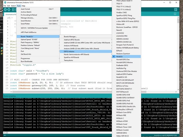
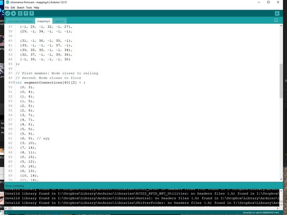
Select your ESP32's serial port. Pick Tools --> Board --> ESP32 Arduino --> Node32s.
-
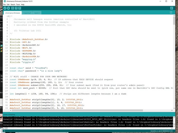
Open the firmware. Change the SSID, password, Gateway, and Subnet to fit your router configuration. Pick an IP address that's unused, preferably outside your router's DHCP range. Pick a recv_port, ideally above 16000.
-
Upload the firmware. Allow the ESP32 to reboot and connect to the network.
-
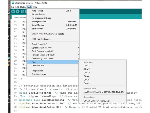
Go to Tools --> Port and look for a Network Port. If you see your selected IP address, you're ready for OTA updates! Your USB cable is no longer necessary.
-
If you don't see your device, I dunno. Ask on the Voidstar Lab Discord!
-
-
-
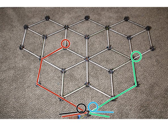
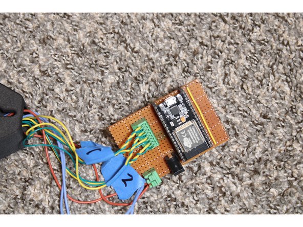
Connect the DIN and CIN pins to the appropriate terminals.
-
Strip 1 (marked with blue arrows in previous diagrams) goes in the terminals furthest from the jack.
-
Strip 2 (marked green) is next
-
Then Strip 3 (marked red)
-
Finally, Strip 4 (marked black)
-
The DIN lines are further from the jack (yellow wires in my picture) and CIN lines are closer.
-
Put the VCC wires into the left 5mm terminal, and the GND wires into the right.
-
Plug in the PSU and plug it into the jack. If your project catches fire, you've made a mistake.
My led-stripe doesn't have CIN. There ist no clock. Is it also working? Any changes at the program necessary?
Werner1973 - Resolved on Release Reply
Then Strip 3 (marked yellow)
I believe you mean marked red.
Gary Woodhouse - Resolved on Release Reply
-
-
-
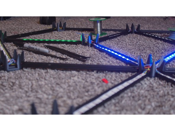
Watch the ripples. They should begin after a few seconds and proceed smoothly through all strips.
-
If one or more strips fails to light up, check for shorts, breaks, and boo-boos. Pads can get ripped off very easily - in that case, remove and replace that strip.
-
If a ripple jumps around on a specific strip, it may be backwards. Adjust mapping.h to reverse it. The nodes and strips are numbered right to left, top to bottom.
-
-
-
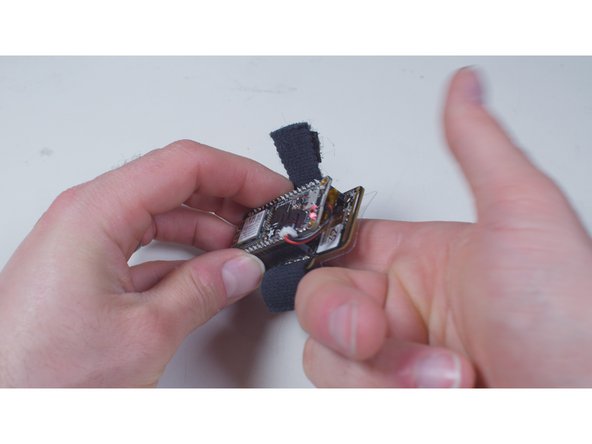
An EmotiBit is not necessary to use the Chromance, but it makes it way cooler!
-
Assemble, charge, and configure your EmotiBit as instructed by the manufacturer.
-
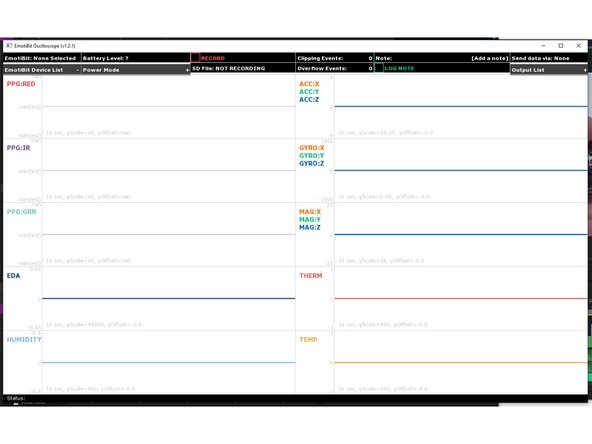
Download, install, and open the EmotiBit Oscilloscope. Then close it!
-
Open C:\Program Files\EmotiBit\EmotiBit Oscilloscope\data\oscOutputSettings.xml (or whatever it is on Linux or Mac). Edit the <output> section to match the IP address and port you put in the firmware earlier.
-
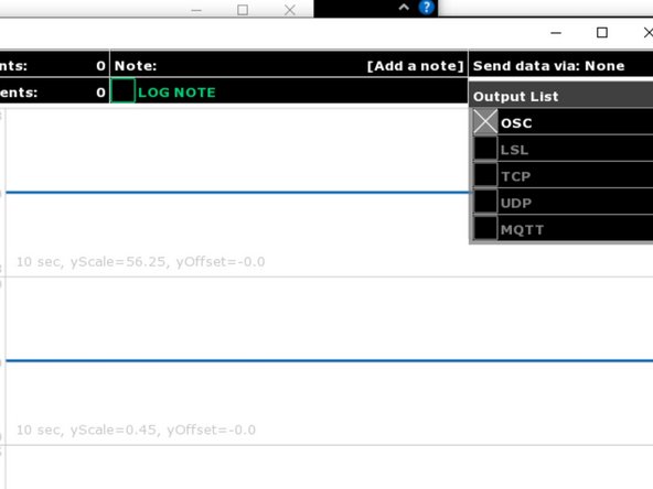
Connect your EmotiBit, and enable OSC in the Output List.
-
-
-
Put your EmotiBit on and ensure data is streaming through the Oscilloscope
-
Your heartbeats and EDA changes should immediately start firing ripples through the Chromance!
-
Adjust the biometric settings in the firmware to respond accurately to your emotional state.
-
Set up a chair, smoke a fat (legal in Colorado) doobie, and enjoy the show.
-
If you enjoyed the project and want to support the next one, head to patreon.com/zackfreedman and give me a huge pile of money!
-
You rule.
No Zack, YOU & VoidStar Labs TOTALLY rule the GIGAnerd project space!
A second will be birthed this month as my son's graduation gift!
Bo Pedersen - Resolved on Release Reply
-


Cancel: I did not complete this guide.
16 other people completed this guide.
31 Comments
@zackfreedman Awesome project!!! Any instructions for using WLED? I won't be using an Emotibit but would like Audio Reactive along with your pre-programed rainbow pattern.
David Cornelius - Resolved on Release Reply
Made my own channels and diffusers and made a junction box for the electronics including a power plug, on off button and usb access for the ESP32.
Adding my own variant here. Took @hastypete bottom node and added a controller box for the ESP32 Dev Breakout Board I used instead of Stripboard.
Timothy Gleason - Resolved on Release Reply
After making my own I was looking at the hubs and had the idea of modifying the hubs to have a single peg instead of 6 all around.
I'm attaching a link to my stl files.
The other thing is that I discovered that you only need two of the special top nodes. The whole structure is light enough for two screws. So I did not modify the "left" and "right" top nodes.
Also I did some creativity for a bottom node. It is 50% larger and has room for the ESP32 board. It also has a support and hole for the standard barrel connector that comes with the standard power supply in the list.
I haven't finished the one with the new hubs, I'll put a photo in the share when I get it done.
I did put a photo of what the "brain" node looks like.
I saw that you are now using WLED for the Chromance. How should I configure it, to make mine work the same way yours does?
Could you create a branch on the Chromance github with the code you are currently using? And since I don't want to use an Emotibit, how well does the WLED integration work without one?
Thank you in advance and also thanks for creating amazing projects. You inspire me to stop procrastinating and make some projects. :)
Felix Schuster - Resolved on Release Reply
I don’t own a 3D printer and the quote for the parts was way too much (which I of course inquired about after acquiring all the other bits) so I redesigned them so that they can be cut out of boards and glued together.
The shop that sold me the aluminum profiles didn’t have enough opaque covers, so I ended up using baking paper instead (it works great, but is finicky to install)
When I finally got to programming, I realized that I don’t understand any of the code, so I wrote the code from scratch as well. For those who want to do that - check out wled (I wish I did when I started)
Long story short - I did everything “my own way” and made a crap ton of mistakes along the way, but the thing works and didn’t go up into magic smoke and I love it.
here it is in all it’s glory - https://media.githubusercontent.com/medi...
feel free to yoink my code / models - https://github.com/darksworm/chromance
Thank you for the guide, Zack! <3
Hello
first of all a big THANK YOU for making your code available,
Unfortunately I have problems with the code :-(
Get an error message in wifi.h
because one more question which pin did you use? and what length are your LEDs
greetings Karsten
Just finished mine. Its on the wall now.
I have made my own variant of the code since I am using WS2812 and 12 leds strips instead of 14.
Ill add a code contribution soon to remove all those ugly magic numbers :P
Thanks again for sharing this really nice project Zach
Simon Benoit - Resolved on Release Reply
Out of curiosity why did you choose to write your own software instead of using something like WLED?
Jeffery Jorges - Resolved on Release Reply
@zackfreedman Would you consider sharing your WLED config for the Chromance? I’d like to do the same.
The project was originally built for a video sponsored by EmotiBit, a biometric wearable company. I decided it would be easier to write my own firmware from scratch than attempt to integrate WLED and EmotiBit. I think there’s actually a binding now, but it didn’t exist at the time. For what it’s worth, I actually do run WLED on my personal Chromance now.
I love the guide and the channel keep up the great work! Can’t wait to give this project a try.
Jeffery Jorges - Resolved on Release Reply
%#*@.. I’ll have to compare and contribute if possible. I did RTFM and was able to make it work.
Darren Shady - Resolved on Release Reply
in ‘mapping.h’, how did you ID the nodes? Do you have a drawing?
I changed the shape of the assembly and the animations are a bit off
Maxime Moquin - Resolved on Release Reply
The LED’s on each chain of strips are numbered such that LED 0 is connected directly to that chain’s GPIO pin, and the highest-numbered LED is the tail of the final strip in the chain. Unfortunately, there’s no way to automatically edit them, and I’ll admit that the way I structured them is complete nonsense. You’ll need to edit ledAssignments so the LED indices (second and third members of each row) correspond to how you wired them up.
I saw in your youtube livestream that the animations on your chromance are different than the ones on github. Do you happen to have any of those animations you can share? Thank you.
@zackfreedman Don’t forget to share those other animations with us! My newly finished chromance is looking forward to trying them out :)
I’ll push my modified code after I fix some weird behavior with the starburst animation.
What’s the dimensions of the finished product? I really want to build this, but I’m not sure if it’ll fit on my wall.
Gary Woodhouse - Resolved on Release Reply
I made something very similar last year and had a ton of trouble with the wiring too! Your project uses a lot nicer materials than mine and I will definitely be 3D printing those hub caps whenever I get around to improving my current version. How did you mount the finished product on the wall?
This was the one I made: https://www.8wire.io/catalog/component?i...
David Moeller - Resolved on Release Reply
I used 22 AWG ‘LED’ extension; I ‘d recommend solid wire to avoid twisting an ‘tinning’ the wires after stripping. Huge time savings
having a hard time trying to follow where to start the soldering and direction. for example in step 6 .. which is the starting point of the directional flow? for all three red, black and green.. and what do i end the connecting of do and di?
I edited the instructions to indicate the first strip in each sequence with a circle, and to move the arrows further apart. The DO and CO pads of the final strip in each sequence aren’t connected to anything. You will wire and route the DI and CI pads of the FIRST strip in each sequence in Step 7. Also, there are four strip sequences - because of limits of this Dozuki tutorial-generation software, I could not put all four images in a single step.
Hi, also i want to know what i have to change in the code if i used a NeoPixels. Thanks
Luis Felipe Castillo - Resolved on Release Reply
Hi friend.
I am using NeoPixels and they don't have CO/CI pins . In step 11, how should i wire the 8 pin connector?
Luis Felipe Castillo - Resolved on Release Reply
I’m not seeing the code update in the main branch. I see it as a pull request, which looks like what I did as well. Not exactly good with Github….
NeoPixels have Data pins that behave the same as the DO/DI lines on DotStars, but they don’t have any Clock (CO/CI) lines. Just wire them up the same way, but forget about the clock. You could get away with using a 4-pin connector, since you only have one input line for each string.
A helpful hacker added NeoPixel support to the code! I’ve merged in their fork, so pull the newest code and you’ll be all good. Check the code to see which pins to connect the Data lines to.
After making my own I was looking at the hubs and had the idea of modifying the hubs to have a single peg instead of 6 all around.
I'm attaching a link to my stl files.
The other thing is that I discovered that you only need two of the special top nodes. The whole structure is light enough for two screws. So I did not modify the "left" and "right" top nodes.
Also I did some creativity for a bottom node. It is 50% larger and has room for the ESP32 board. It also has a support and hole for the standard barrel connector that comes with the standard power supply in the list.
I haven't finished the one with the new hubs, I'll put a photo in the share when I get it done.
I did put a photo of what the "brain" node looks like.
Chromance Single Peg Support
hastypete - Resolved on Release Reply
Pete,
Love your STL for the bottom node enclosure, but do you have a pic/info on how you stuffed it all in there? I'm about to just go point to point but I'm curious. I know odds of you seeing this are slim/none but figured I'd try.
Thanks!
NOPper -
Correct me if I’m wrong, but your number for parts are off here based on the images. We’ll need to print 1 less RegularNode.stl and an additional TopCenterNode.stl to use at the bottom most node, right?
Jeffery Jorges - Resolved on Release Reply
You’ll need to put a RegularNode on the bottom so your can route the wires out of the bottom.
Zack Freedman -
I was making one of my own then I saw your pizza table … simple and sweet design and really great fit with the aluminum channels.
Simon Benoit - Resolved on Release Reply
I'm intrigued. What is the "pizza table"?
hastypete -